DAMPER
PRESSURE RELIEF / NON-RETURN DAMPER
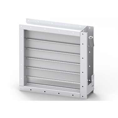
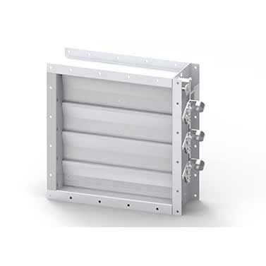
HI AIR KOREA(HAK) PRESSURE RELIEF DAMPERS are used to relieve over pressure through ventilation ducts. When the pressure exceeds a certain level, the blades are opened by the air pressure applied to damper blades.
Opening pressure
- : 30~150 Pa (When installed in the horizontal duct)
- : 50~170 Pa (When installed in the vertical duct)
HAK NON-RETURN DAMPERS are used to prevent backflow in ventilation ducts.
HAK PRESSURE RELIEF DAMPERS and NON-RETURN DAMPERS are provided with counter weights.
- FEATURES
- The maximum size of PRD & NRD is 1200 mm(W) and 1200 mm(H).
PRESSURE RELIEF DAMPER (PRD)
- When the pressure exceeds a certain pressure, the blade is opened by the force of the spring, so the pressure is automatically controlled. Normally this is installed in Airlock, Natural Exhaust Duct.
NON-RETURN DAMPER (NRD)
- The damper installed to prevent the backflow of air inside of duct is called a NON-RETURN DAMPER or a BACK DRAFT DAMPER. It is installed in the middle of the airflow or at the end of the supply.
TYPE 별 BLADE LEAKAGE
Type Blade leakage Shaft size (mm) Blade type Length (mm) PRD-1 & NRD-1 Not applicable Φ12.7 Single skin 200 PRD-1 & NRD-2 Class2 Φ16.0 Double skin 250 STANDARD CONSTRUCTION
Part Material Thickness Finishing Casing Carbon steel 3 ~ 10 mm Painted / Galvanized Stainless steel 3 ~ 10 mm Passivation Blades Stainless steel 1.5 mm x 2 (Double skin) Passivation Shafts Stainless steel Φ19 Passivation Linkage Stainless steel 3 ~ 8 mm Passivation Linkage bar Stainless steel 3 ~ 8 mm Passivation Side seal Stainless steel 0.25 mm - Bearings (Bush type) Stainless steel or Brass - - - OPTIONS
- ATEX Certificate
- Witnessed leakage test
- CAPACITIES

GENERAL ARRANGEMENT DRAWING
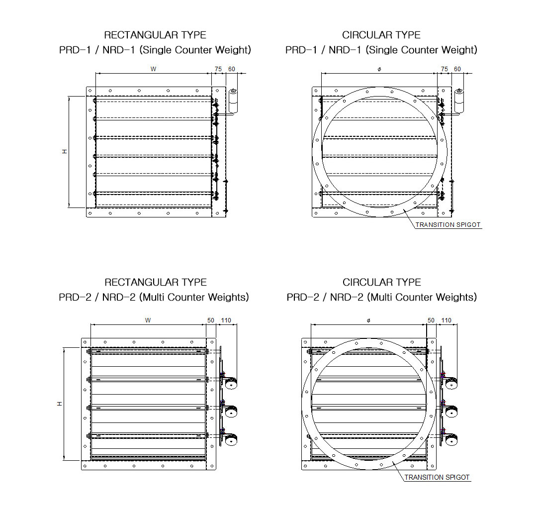
NOTES
- 1. Flange drilling shall be in accordance with ISO 15138:2007 ANNEX E
WEIGHT FOR PRESSURE RELIEF / NON-RETURN DAMPER
Weight (kg) for PRD-1 / NRD-1 Type Height
(H, mm)Width (W, mm) 100 200 300 400 500 600 700 800 900 1000 1100 1200 100 7 9 12 15 17 20 23 25 28 30 36 38 200 8 11 14 17 20 22 25 28 30 33 39 42 300 10 13 16 19 22 25 28 30 33 36 42 45 400 13 16 19 21 24 27 30 33 36 39 45 48 500 15 18 21 24 27 30 32 35 38 41 48 51 600 17 20 23 26 29 32 35 38 41 44 51 54 700 19 22 25 28 31 34 37 41 44 47 54 58 800 21 24 27 30 34 37 40 43 46 50 57 61 900 23 26 29 33 36 39 42 46 49 52 60 64 1000 25 28 31 35 38 42 45 48 52 55 64 67 1100 31 34 38 42 45 49 52 56 59 63 67 70 1200 33 37 40 44 48 51 55 59 62 66 70 73 - Weights above are with casing thickness of 3 mm.
- DOCUMENTS
For more information, please contact the sales manager.
1 Installation, Operation and Maintenance Manuals DOWNLOAD 
1


